Procedural Terrain Rendering How-To

I see. Soundslike a different approach, yes. I need to think a while about it. Right now it seems more “natural” to me (says nothing about the better process!) to draw the planes directly “where they need to be in the end” (starting from [-1,-1,-1] to [1,1,1] object space, the planet centered at 0,0,0, normalise, push to worldspace (out of -1 to 1 bounds) by applying the radius, applying additional noise to push them a little further, and then move the plane to its location in the universe. With each normal targeting away from the plane, and no further transform (ignoring that there are indeed transforms, but not for the planet itself which I handle at 0,0,0, but when I need to transform the planet/planes to their final position within the universe).
But interesting hint, need to think about it what it could mean pro and con-wise and what it would mean about changing the implementation strategy.
Anyway I am going to document the code of the classes where I create the planet & planes in detail to hand it out to you. Its overall not a lot off code thanks to the procedural idea- its less code with more “thoughts” about it.

And, thanks for reviewing the post beforehand!

EDIT:
I checked my azimuth calulcation by using quadtreeTerrain.centervector.normalized (so within [-1,1] range) instead of quadtreeTerrain.WScentervector (which is the same vector but additionally multiplied by the radius). It gives a perfect result (at least for non-splitted planes, I need to test the calulcation under split conditions too), see below. So the issue with azimuth and the other angle calulcations have been that, although the vector should be the same, there seems to be a precision issue which after pushing the vectors away from [-1,1] - which causes the vectors being slightly off.
So now I should be able to rotate the vectors easily with your method to vector3.right and then vector3.up. Will switch to that this evening and see if it overall works.

float azimuthAngle = Mathf.Atan2 (quadtreeTerrain.centerVector.normalized.z, quadtreeTerrain.centerVector.normalized.x)*Mathf.Rad2Deg;

Regarding your questions above - not aligning the patch’s bbox edges to the x-z axes will definitely have an effect on the AABB-Sphere collision check - but it’s hard for me to say how significant that will be. But the ‘correct’ solution shouldn’t require much (if any) more computation than you’re currently doing. So my suggestion is to try and get the BBOX approach working, which I’ll gladly help out with, but if it’s not happening then try an altogether different approach (i.e. distance to center vector, or distance to corner vectors, similar to what you had before), because you likely wouldn’t be benefiting from the extra computational complexity (not to mention the code will be that much harder to interpret when you revisit the project years from now!).

EDIT: Cool! Hope it works! :slight_smile:

Seems like its working now with the rotation. I did a short documentation of it. Below.
However there is one issue left, I’ll adress this in the next post.

So the BBOX approach is nearly working. However I noticed one maybe last issue. Whily flying around the equator, I noticed that sometimes a plane, typical one which has been behind the horizon and a low resolution (near 0, so large plane) starts to split very late. It cannot be a quadtree parsing issue, because when I fly the other way round or start in front of it, it splits normal. My first though was it might be due to the camera being with the Y-coordinate below AABBmin. But I’ve tested the AABBvsSphere check manually, and so far it doesnt matter if the camera is below or upside the AABB. Could be the horizon-/visible sphere culling. Need to check that.

EDIT [2015-06-28]: Fixed. It was due to a problem in the algorithm I used to get the nearest point of the plane (used for the visible sphere culling). But, since now the BBox-works I dont need that extra calculation anymore. The only thing that remains is my plane volume check that I call before the visible sphere culling (and which overrules the visible sphere culling so that splits near the surface do start). visible Sphere culling itself now uses the four edges of the plane again.

Looking good :slight_smile: time for code-cleanup, see if there are performance optimization chances, code-documentation, and the video

hereby a first video capture. Still searching for a good tool that does not try to install malware and captures in dgood quality without stuttering, or compression artefacts and good resolution. But anyway…
I left the debug render on, so that the splits (red) and merges (green) can be seen.

There you go…

Will watch now! I use Open Broadcaster Service to record my screen, it’s excellent.

EDIT Great work, and I thoroughly enjoyed your song! Are you using guitar samples or recording that??

Excellent documentation. In my renderer, the bounding box itself is axis aligned, although yes the patch is not perfectly square due to distortion at greater lat/longs. But - the distortion I get is very small, likely because I’m pre-distorting my nodes to account for the stretching. This complicates the quadtree structure somewhat, but fortunately the amount of extra computation is small. I’ll paste the code below - but please note it is not necessarily intuitive and unfortunately I’m a bit pressed for free time lately so a more detailed explanation/visualization may have to wait.

for (int row=0; row<=edgeDivisions; row++){
        
   float vAmount = ((2f*row)-edgeDivisions)/((float)edgeDivisions);
      
      for (int col=0; col<=edgeDivisions; col++){
        
         float hAmount = ((2f*col)-edgeDivisions)/((float)edgeDivisions);
            
         Vector3f current, verticalDist, horizontalDist;
            
         if (buildDistributed){
            //Distributed
            verticalDist = Vector3f.Scale(vertical, (float)Math.tan(vAmount*Math.PI/4f));
            horizontalDist = Vector3f.Scale(horizontal, (float)Math.tan(hAmount*Math.PI/4f))
            current = Vector3f.Add(normal, Vector3f.Add(verticalDist, horizontalDist));
         } else {
            //Standard
            current = Vector3f.Add(normal, Vector3f.Add(Vector3f.Scale(vertical, vAmount), Vector3f.Scale(horizontal, hAmount)));
         }   
            
         if (normalize) current.normalize();
                                           
         ...

      }
}

Thank you for the kind words and the Open Broadcast Service hin. Will give it a try and record a better quality video (the current capture really lacks image quality).

I play guitar myself and like to cover U2 songs or write own tracks, no samples. All you hear was actually played and recorded by guitar (also the “synthesizer”-like sound thanks to guitar effects), only the drums were modelled in the audio software (Cubase).

You two should get a room. :wink:

Best recording software is Nvidia Shadowplay, it’s standard on any modern Nvidia card, records directly from the GPU at 60fps, AMD has an equivalent feature…

If you are concerned about cube-sphere distortion, you can always go with a ico-sphere.

Sorry for the crappy formatting above. I could have sworn I had a prototype to demo this, stand by…

EDIT Can’t find it, bummer. I can make a quick prototype to demo the concept if interested.

Basic idea is that by using the vertex “patch coordinates” (which either range from 0.5 to .5 or -1 to 1, i can’t remember), the distribution function uses tangent to ‘pre-distort’ the vertices. Those closer to the edges of the patch are “squished inward”, so that once everything is normalized to a sphere, the vertices are evenly distributed.

There you go, good quality video. Great tool. Thanks for the hint for pre-distort, will investigate that, however if I dont get into it too fast I’ll switch to the next topic anyway as it works nicely as it is. In the video you can see in the end that I prepare local space fog (based on global noise results based on players position). After adding dark cloud particles this will give a nice effect. One of the next topics:

  • Water Surface
  • Surface collision (right now you can fly through the planet, which makes it hard to work on surface details).
  • Procedural texturing of planes (grass, rock, etc.)
  • Atmosphere Shader
  • Noise investigation (for low level planet surface)
  • Space travel effects (warp effects, space particles)
  • Additional ship controls

@NavyFish: Documenting the code in order to hand it over. Would be really nice if we can continue to research that topic together.

@Cybercritic: I’ve been starting with the icosphere before the cubesphere. While it was really beautiful in terms of regular planes and very little code to produce it, I found it hard to do LOD with it. Because you always had to increase the detail of the whole surface (because its one plane object) instead only increase the visible area in front of the camera. But maybe there are tricks to workaround that or just a different kind of LOD strategy, but I’ve found it very hard to do LOD in combination with the icosphere.

Joerg, great stuff. You’re inspiring me to get back into my own procedural planet project, which has been untouched since early 2012. I look forward to checking out your code and will be happy to brainstorm ideas or help out with implementation.

My bruteforce test to create a separate Waterbody at “noise = 0” and same center as the planet failed. Too much Z-fighting. Guess this will be nearby impossible to create.

So I avoided this topic for the moment :wink: and started to investigate a bit into better textures.
Current approach: Combine the current ColorTexture (based on the height) with AtlasTexturing.
While reading from the AtlasTexture, get the pixelinformation three times (at higher repetition, medium repetition, lower repetition). And combine the resulting 3-layer texture from the Atlas with the ColorTexture.

As expected, patterns are an issue. My ideas to get rid of that:

  1. At low lever nodes, the ColorTexture should be weightended more than the information from the AtlasTexture so that texture details get more visible only at lower height (that should be most important change).
  2. Blend a bit between different texture types.
  3. Consider the pitch when choosing the terrain type, not only simply the height (need to see how I determine and store this information)
  4. Add a little little bit of randomness when reading the pixels from the TextureAtlas.

I’ll start thinking about the texture issues you’ve brought up, although just off the top of my head, I wonder if you could do a direct texture mapping (one lookup vs three) and use a different texture at different scales? Kind of like using mip-mapped textures - the LOD determines the mip level. You’d need infinitely repeatable textures, however.

Anyway, something I can actually help out with: determining terrain slope (pitch).

I calculate my terrain on the GPU in two passes - the first generates the terrain by ‘distorting’ an input patch using noise functions, and then the second pass calculates the normal vector for the terrain. The angle between the terrain’s normal vector (at a specific location) and the normalized vector from the planet origin to that same location will give you the terrain slope. You can also get the partial derivative (i.e. the slope amount in each axis - i.e. the gradient) using the normal vector, though I’d have to think about that for a bit. But chances are you only need total slope anyway.

Here’s the way I do it. Note that this is before rotating the patch into it’s world-space position, so here the patch lays along the X-Z plane, with the Y-axis being up:

Vector3D leftVert = vertex to the left of the current vertex;
Vector3D rightVert = vertex to the right of the current vertex;
Vector3D upVert = vertex "above" the current vertex;
Vector3D downVert = vertex "below" the current vertex;
float i = leftVert.y - rightVert.y;
float j = downVert.y - upVert.y;

float gridSpacing = distance between vertex grid elements (i.e. rightVert.x - centerVert.x)
Vector3D normal = new Vector3D(i, 2*gridSpacing, j);
Vector3D normal.normalize();

Keep in mind you’d do this for EACH vertex in your patch. Your border vertices will not have enough information - i.e. the rightmost vertex wont have another “right” vertex. There are two options - you could take the “half” normal, where:

float i = leftVert.y - centerVert.y;
float j = downVert.y - centerVert.y;
Vector3D normal = new Vector3D(i, gridSpacing, j);

But I don’t like this approach because it’s too rough of an approximation, and you’ll get noticeable lighting and texture discontinuities the borders of patches (even those of the same LOD). The approach I took instead was to make my “proto terrain patch” (n+1) * (n+1) vertices (where n is the number of vertices in the final patch), so that I had a “skirt” around the border of my patch which I could use when calculating normals. Just make sure you don’t attempt to calculate the normal vectors for these skirt vertices. Once the normals have been calculated you can throw away the skirt vertices.

I’m sure this same algorithm could be used on the patch in “world space”, but it will complicate the math as you’d need to take the dot product several times I’d imagine.

Anyway, once you have the normal vector,

float slope = 1/max(dot(normal, Vector3D.up), .001f);
// Vector3D.up is (0,1,0)
// max function is used so that slope is not Zero, which would cause division by zero errors later on (although you could simply check for that case instead of forcing it to not be zero)

I used the slope to help determine the appropriate terrain color (or texture) as such:

//GLSL
vec3 color = mix(snowColor, slateColor, smoothstep(1.5, 1.6, slope + .2*fBm(worldSpacePosition, .4f, 1.918, 4)));

Basically it blends between either the snow or rock color based upon the slope - which I’ve additionally perturbed using some high-frequency noise to add variety. That’s the coloring function used in the “snowy mountains” scene of the demo video I posted awhile back.

Having the normal vector is critical, because it lets you apply specular & diffuse lighting, bump mapping, etc. All fun topics - although you really should start learning about shaders if you want to get deeper into those techniques! I’d be happy to teach you more about those from a purely OpenGL perspective (lots of similarity to DirectX), but I can’t speak to how they’re implemented in Unity.

Hope this helps!

I thought of using textures of different scales first. I liked the idea of using only one (highres) texture, and do the visual downgrade by code. However, after thinking about it, doing multiple texture lookups just for each pixel to get a lowres version is probably overkill and not optimal. And creating textures at multiple resolutions in Photoshop is done fast.
So ok. Decision done, I am creating a “QuadtreeTerrainTextureProvider” class that holds all types of textures at different scales/LODs. I think I’ll organize them in an array per texture type, lowest at index 0, highest at index 22 (probably the max depth I am goind to do in my quadtree, and in the range of ~50cm at an earth scale planet which suits the texture’s scale, so that each quadtree node depth has its own texture type index.
Highest texture will be at 2048x2048, and then I create downgraded version by the power of two. So per texture, there’ll be 2048x2048, 1024x1024, 512x512, 256x256, 128x128, 64x64, 32x32, 16x16, 8x8, 4x4, 2x2, 1x1.

Should be done fast, will post the results and see where it goes.

BTW… amazing post NavyFish! perfect explanation, and wow great and simple approach to get the slope by checking the normal vectors. Thats so simple that I didnt think of it (I was thinking in a too complicated way to compare all the noise results etc.). Perfect, can be easily integrated into the QuadtreeNode creation process and being stored there.

Glad the post on Normals helped. Will gladly clarify anything if need be, but the concept really is that straightforward.

If you really wanted to ‘reduce’ the texture sizes in code, you could write a separate program to do so. But if you’re only working with <10 textures then your photoshop approach is probably faster. But - if you decide to do it in code, check out “Mip-Mapping” which is the process OpenGL (and I assume DirectX) uses. Whenever you give OpenGL a texture, if you have the “Mip Mapping” flag enabled, it will automatically generate a set of power-of-two size reduced textures from it, down to a minimum level (typically not as small as 1x1). Each of these levels are called “Mip” levels, although I forget why. Anyway you may be able to borrow some pseudo code from their implementation. Note that the use of texture filtering on the reduced images is critical to the resultant image quality (otherwise, you might as well just multiply your texture coordinates by a scale factor and be done with it (single-sampling a large texture).

Quick update since it’s fairly late and I’m off to bed.

Been playing around with Unity3D this past weekend (had Friday off too), and must say I’m impressed. It’s surprising how much flexibility they can achieve while still presenting a fairly consistent ‘API’. That having been said, there are plenty quirks and a few kludges, particularly with what I’m working on. But less than other frameworks I’ve used, and those didn’t provide half of the features Unity does. So, great!

This exploration really begun when I realized you could in fact perform GPGPU (general purpose computing on the GPU) through unity using DirectCompute (D3D11 only). One thing led to another, and I decided to see if I could generate some terrain on the GPU. ~15 hours later and, well, here we are. Now, I’m not going to say it was particularly straightforward… in fact, it feels a bit hacky. Particularly because, in order to leverage the physically-based surface shaders (Unity 5+), I needed to use a mesh. So after dispatching my thread group to the Compute Shader on the GPU which calculates the height at each point on the terrain using Simplex noise, when it comes time to actually draw the patches, I had to draw a “dummy” mesh (with the same # of vertices as those I computed on the GPU) that has junk data for the vertices, and use a custom vertex shader in front of the stock surface shader to transform those vertices to the ones I just computed in the Compute Shader. That’s the big hack - but it works, and I’m sticking with it.

(By the way… Unity limits the number of vertices in a mesh to 65k. Not even 65,535, which would be 256x256, but 65K… grumble. So I’m doing 224 vertices per edge, so 224x224 - 224 is a multiple of 32 (x7), which was efficient for my Compute Shader’s thread group layout. anyway…)

The terrain heights never leave the GPU - once calculated they’re stored in a “structured buffer”, and the vertex shader reads into the same buffer to transform the dummy mesh’s vertices. Once that vertex shader completes, it passes its results to a stock Surface shader, allowing me to get all that physical rendering goodness for free (Had I not wanted to use the stock surface shaders, I could have avoided using the dummy mesh).

I did a basic benchmark on my GTX 580m (which is starting to show its age), and was able to maintain just over 65 fps while calculating 36 new patches (of 224x224 = 50,176 vertices each) every frame @ 14 octaves per vertex (which is probably way overkill). I think that’s pretty good! Of course, in an actual planet engine, once the patch was calculated I’d hold onto it as long as I could (to be freed only when VRAM was needed for a newer patch), whereas here I’m dumping and rebuilding the data every frame. Now, mind you, I’m not reading any data back to the CPU - that takes much longer. I’ll eventually need to do so for at least two reasons: 1) To calculate bounding boxes - but there I think I’ll do a parallel reduce on the GPU (basically it determines the min/max vertices in a parallel manner) on each patch, and then retrieve that data (so 2 floats per patch vice 50k… that will be much faster) - and just use the min/max possible height in the meantime, since that will have to be an asynchronous process otherwise the whole pipeline will stall. 2) is the harder one - physics. If I’m going to do any kind of collision detection, I’m going to need to either do it on the GPU (which would solve all the problems, BUT I think would be completely outside the scope of unity and require basically all physics calculations, not just collisions, to take place on the GPU…), or be very very picky about what terrain data I send back to the CPU (those transfers are slow, and laggy, and will chunk the framerate in a heartbeat. So probably stuff like only sending the patches nearest to the camera, and doing so at a lower vertex resolution than max LOD, etc). I don’t plan to worry about that just yet, but it definitely is a consideration when doing GPGPU.

Anyway, like I said I’ve been really impressed with Unity. I’ve basically achieved the same amount of work in the past 3 days as I did in 3 months working on my planet renderer. Now, granted, A) I was writing an entire engine, not just a planet generator, B) I could only dedicate 5-10 hours/week, and C) I was a much more novice programmer. Not to mention, I’ve been able to leverage the lessons learned from that project (and recently refreshed thanks to this thread!), as well as several bits of code. Regardless, it’s without a doubt easier to develop code in Unity due to both the existing libraries and the ability to ‘visually debug’ - clutch stuff!

What’s next? I’m probably going to go all the way on this one, and implement the full scope of techniques we’ve been discussing throughout this thread. Once all that technical stuff is done, I’m going to explore the more artistic side of things. Hopefully I can get Unity to recompile a shader at runtime, so I can hot-edit the terrain generation functions and play with different functions, etc. Maybe even explore ‘non-procedural’ content mapping - i.e. using a base DEM or texture to ‘influence’ the underlying generation algorithm.

Heck, I might even make a game out of it. I’ve wanted to build an RTS/Civilization-style game for awhile, and doing so on a procedural planet would be fun.

So, yeah! I’ll post a screenshot, but it’s ugly. Everything’s using 1 texture, and I haven’t tweaked the noise function parameters at all (actually the terrain generating noise function was a direct copy-paste from my last project!) - but everything is functioning and the terrain is being generated on the GPU which has been the whole point of this test so far.

That’s all I’ve got for now! Let me bring this excited, sleep-deprived rant to a close. Talk to you soon!
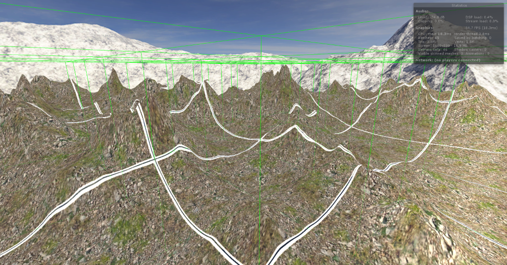
1 Like

Wow. Cool stuff, and impressed that you fully tackle this on the GPU (really need to get into shaders soon). And also that you got this result this fast! I agree Unity3D is a nice engine to use for that topic. Glad you like it. Would be kind if you can let have me some inside look how you work with the shaders once you are done.

I continued to work on the texture and code cleanup. Right now I do the plane textures by a combination of a material texture (different material textures per type and per resultion, as you proposed) and color texture. Screenshot below. You dont notice the material texture in that height, but thats what I wanted to achive, however I want to teak it a little bit (making the texture more and more visible than the colortexture, the more you approach the surface). Patterns are hardly visible now, yeah :-). I right now work on blending between material types and calculating the slope. Texturing based on those two things, there should a nice variance. I will leave it as is then for the moment. And first of all finish my code cleanup, which is nearly done, and sent it to you (hopefully this weeking).

Like I said, I’d be happy to help out with shaders. Unity shaders are a bit ‘sandboxed’ compared to straight-up HLSL shaders, but you strip all of that away and use “pure” vertex/fragment shaders without the ShaderLab wrapping. They actually have a decent shader tutorial in the Unity Manual.

Looking forward to browsing your code! And I’d be happy to share mine, soon probably, before it gets more complex.

So I’ve finally managed to put together a good demo of that vertex distribution scheme I was describing - the one which prevents vertices from becoming ‘bunched up’ near the corners of the Quad-Sphere’s faces. Here’s an imgur album which clearly shows the “normal” method, followed by my “distributed” method.


Best of all, the code is easy:

for (int r=0; r<nVerticesPerEdge; r++){
    for (int c=0; c<nVerticesPerEdge; c++){
        
        //put vertices in the range -1 to +1
        float h = (2f*c/(nVerticesPerEdge-1f))-1f;
        float v = (2f*r/(nVerticesPerEdge-1f))-1f;
    
        //perform the distribution
        h = tan(QUARTER_PI*h);
        v = tan(QUARTER_PI*v);
            
        point.x = patchRadius*h;
        point.y = patchRadius;
        point.z = patchRadius*v;
            
        point.normalize();
        point.mult(patchRadius);
                        
    }
}

This creates a patch whose “up” direction is the +Y axis, and which lays at ‘patchRadius’ from the origin.

Hi, I’ve been working on a procedural planet generation system for a while now and have implemented pretty much all of what you’ve listed in the original post in the Unity engine (I still need to do a fast occlusion culling implementation but haven’t as I haven’t really felt the need to). For noise generation I went from full CPU-bound to full GPU-bound and realized full GPU can be a little slow when getting the data back from the GPU for collision detection (even slower than on the CPU because it can’t be multithreaded) and ended up doing just textures on the GPU and a multithreaded system on the CPU (my patches are a lot less dense though at 32x32 vertices) which works quite well and doesn’t kill the framerate every few seconds when flying over the terrain at high speeds. But there’s one thing I haven’t seen you list here and that is the precision limitations on the GPU when generating noise at high depth levels (>15) which will leave nasty artifacts - this is an issue I still haven’t completely overcome and is probably the most annoying issue that I’ve run into (even more-so than the other precision issues like vertex jitter and z-fighting).

Link to image:https://dl.dropboxusercontent.com/u/88635652/GPUTextureProblem.png

I’m wondering if you or anyone else here has investigated this issue yet and tried to resolve it.

GPU -> CPU is definitely slow - well, to be more precise, the transfer itself isn’t slow, but there’s a latency involved since the GPU must flush its pipeline before downloading the data. I’m looking into ways to mitigate/hide this latency myself, but haven’t implemented terrain collision/physics yet so don’t have a good answer. Will certainly report back if I come up with anything worthwhile.

The picture you shared - fascinating… are you sure that’s not an error or precision artifact in the normals calculation? The terrain positions look perfectly fine. But assuming it is in fact a position precision issue - I haven’t encountered it, likely because I generate terrain in “patch” coordinates, where the coordinate system origin is at the center of the patch at the ‘50%’ noise value. Terrain ‘displacement’ can range from -20 miles to +20 miles and still have enough precision using 32 bit floats for sub 1-cm epsilon.

Then when I go to draw the patch, it’s translated to its ultimate world-space position which is about 4,000 miles from the center of the planet for an earth-sized globe.

So I suspect you’re generating the patch in either “world-space” coordinates, or “planet-space” coordinates, such that 0,0,0 is at the center of the planet. Moving that origin closer to the patch when generating it will buy you enough precision.

(Apolgies for rambly post, too much scotch!)