I’ll share, gladly.
One of the keys to speeding things along is only performing the test when necessary. There are many ways to reduce the number of horizon occlusion checks you actually need to perform, such as only doing so once the camera has traveled a certain distance relative to the planet since the last check. Whenever an occlusion test is performed against a patch, I record the location of the camera relative to the planet (i.e. cameraPos - planetOrigin) at that moment. The next time I go to test against that patch, if the camera’s current position relative to the planet isn’t sufficiently far enough from its relative position the last time it was checked for that patch, I skip the test and simply reuse the last result. The ‘sufficiently far enough’ distance should be different for each LoD - I used a look-up-table with values that equated to approximately 10% of a patch’s diameter at each LoD, although this number is best determined through experimentation (keep a count of how many tests you skip per frame).
Another way to reduce the number of tests is to use frustum culling. I haven’t yet implemented it, but at some point intend to try out this approach: flipcode - Frustum Culling . However you do it, do it prior to the horizon test.
Next, I calculate the radius of the “visibility sphere”. The “visibility sphere” is centered on the camera. If the camera was in orbit around a perfectly smooth planet (spherical planet). the radius of the “visibility sphere” would be the distance from the camera to the furthest point on the planet’s horizon. Nothing is visible beyond this distance.
If the planet is NOT perfectly smooth, however, we have to extend that sphere. Image a very tall, steep mountain sitting just beyond the smooth planet’s visibility sphere - you should clearly see the mountain’s peak. So, when dealing with a featured terrain, we need to modify the calculation of the visibility sphere. I do this by taking into consideration the maximum possible height of the terrain. Please reference the following image for the derivation of that equation (this graphic is something I produced three years ago to help myself develop the equation, and then help me remember it three years later!):
(You may want to open it in a new tab and zoom in to see the red text)
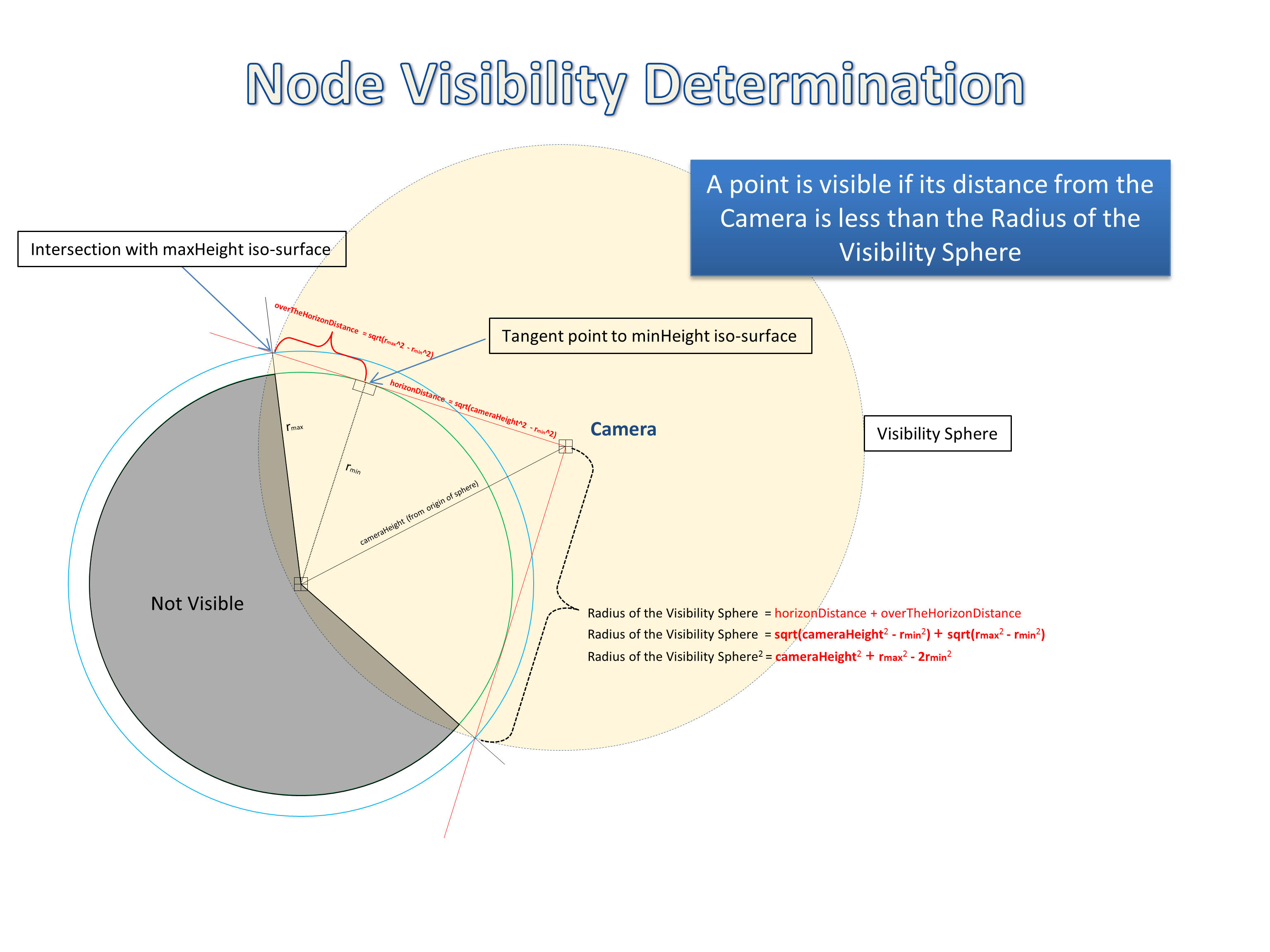
With the radius of the “visibility sphere” having been determined, you could simply test each of the vertices of your terrain patch bounding boxes to see if their distance to the camera is greater or less than the radius of the visibility sphere. If any vertex is less than the radius, subdivide and re-test the children patches.
I am using a slightly more complex method, simply because case does exist where no bounding box vertex falls within the visibility sphere, but part of the patch does. (i.e. imagine a 2-D square at the origin, with vertices at (1,1), (-1,-1), etc. Now image a sphere of diameter 0.5 placed at (1.2, 0). The sphere clearly intersects the box, although none of the box’s vertices fall within the sphere).
To do so, I use an AABB (Axis-Aligned-Bonding-Box) - but not in the traditional sense. Normally an AABB is aligned to the world axis, regardless of the object’s orientation. This causes the dimensions of the AABB to change as the object (unless it’s a sphere) changes orientation. At certain orientations, the AABB is not a very tight representation of the object.
Instead, I use the model’s native coordinate system, so that the AABB matches the patch much more closesly. Here’s what I mean
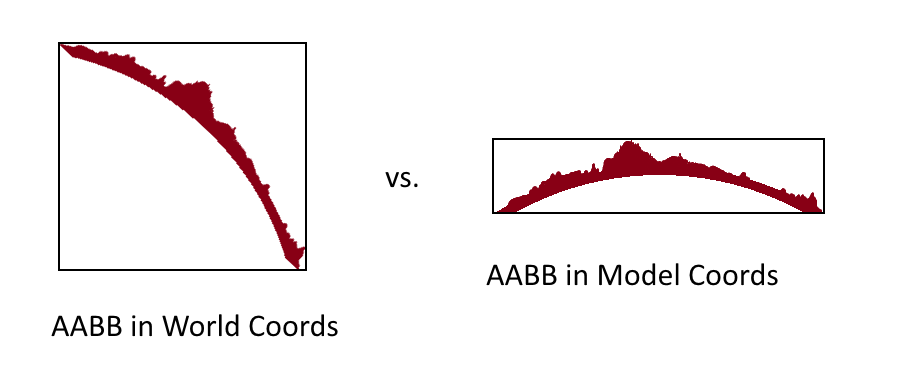 :
:
(Hooray for Paint.net!)
Next, I transform the camera (and hence the visibility sphere) into the model’s coordinate system. Finally, I conduct a simple AABB - Sphere collision check between the visibility sphere and the patch’s AABB.
This process is integrated directly into my patch LoD determination: If the patch falls within the visibility sphere, I don’t immediately subdivide it and test it’s children. Instead, I check it against yet another camera-centered sphere: A “LoD Transition” sphere. That is: each level-of-detail has a certain ‘optimal distance’, which keeps the “vertices per pixel” in an appropriate range. I calculate this range band for each of my LoD based upon the monitor’s resolution, the camera’s field of view, and the number of vertices per patch. I don’t have the derivation of this equation written out, but it was fairly basic and made several worst-case assumptions (i.e. face-on angle to each patch, etc), in order to determine how close you could get to a patch before the number of pixels between each vertex in screen space exceeded a certain threshold.
So, with an LoD distance band look-up-table, I next check the patch against another camera-centered sphere with radius from this table based upon the patch’s LoD. If the sphere collides with the patch’s AABB, then the patch is too close to the camera for its current level of detail, and must be subdivided. If not, it’s at the appropriate LoD - add it to the drawing queue!
Hope this was helpful. As always, I’d be happy to elaborate on anything that may have been confusing.
I also have a couple of proccessing.org prototypes demoing these concepts… let me see if i can dig them up and post them somehwere…

 :
:
 ). Anyway its an interesting topic where situation between headaches and “yeah, it works” nowhere changes so frequently and often


